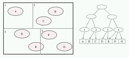
Figure 1: Space subdivision (left) and the corresponding BSP tree (right).
Jaroslav Křivánek, Vojtěch Bubník
{xkrivanj, xbubnik}@cs.felk.cvut.cz
Departement of Computer Science and Engineering
Czech Technical University, Faculty of Electrical Engineering
Prague, Czech Republic
In this paper, we present a method for finding the nearest ray-object intersection. Our method uses binary space subdivision. To accelerate the tree traversal time, we use the technique called rope trees. A comparision of results between traversing BSP tree with and without rope trees is included at the end of this paper.
KEYWORDS: ray tracing, spatial data structures, ropes, rope trees, spatial subdivision, BSP tree.
Ray tracing is a widely used rendering technique for producing realistic images that simulate specular surfaces. It requires testing of many rays to determine intersection with objects. A way of reducing the computational cost of ray tracing is to minimize the occurence of one basic operation, the ray-object intersection test. The simplest method of determining the ray-scene intersection is to test the ray against each object and to remember which object has the nearest point of intersection. This is extremely slow and can be greatly improved with the use if scene structuring.
For nearly all object of the scene, an intersection test is a nontrivial computation. To speed up the intersection test, a bounding box is placed around the object. If the ray doesn't intersect the bounding volume, it doesn't intersect the object inside. Otherwise, the ray-object intersection must be computed in usual manner. This is the simplest case of scene structuring, but it can be generalized with the idea of hierarchical data structure.
There are two main classes of hierarchies used to order the scene. Object subdivision clusters the objects, recording the space that each object inhabits (hierarchical extent tree, [3] [5]). Space subdivision subdivides space, recording the objects that intersect each region ([2] [4] [8] [1]).
The binary space partitioning (BSP) tree [2] [4] is a common type of space subdivision. Initially, the BSP consists of one node, representing the bounding volume containing all objects of the scene. This volume is divided using a splitting planes perpendicular to one of the major axes. Each leaf of the BSP contains references to all objects that intersect it. The division continues until the given minimal number of objects per leaf is reached or the depth of the BSP reaches the given maximal value.
Figure 1: Space subdivision (left) and the corresponding BSP tree (right).
An important factor influencing the resulting properties of a BSP tree is the criterion for positioning the splitting planes. It was studied by Kaplan [4] and MacDonald and Booth [6]. Kaplan simply placed the splitting planes in the center of the parent volume.
Better way is to position the splitting plane so that the probability of intersection of arbitrary ray with an object in the two new leaves is roughly the same. In [6] a simple heuristics for finding the optimal position of splitting plane is used. This technique is also described in [8].
A ray-traversal algorithm works recursively. If the ray hits a node of the BSP tree and the node is not a leaf, it is tested against the splitting plane of the current node. If the ray is not cut by the plane within the node's box, the traversal algorithm continues in the appropriate child of the current node with the same ray. Otherwise, the ray is cut by the plane and the traversal continues in both children with the modified ray.
If the node is a leaf and the intersection with an object is not found the algorithm returns to the first node, in which the ray was divided in two. If no such node exists, the ray doesn't intersect the scene at all.
In this section we present the concept of ropes and rope trees for BSP tree. We adopted the technique from [6] and [8]. We describe rope trees construction and ray-traversal algorithm using these data structures.
The resursive ray-traversal for all types of rays (primary, secondary, shadow) always starts from the root node of the tree and continues downwards. It proceeds identifying pierced nodes until it hits an object. In most cases a ray intersecs an object very close to it's origin and thus the down-traversal from the root can form a large portion of the whole traversal time.
To gain from a coherence between the primary and the secondary rays, it would be good to eliminate the down-traversal for secondary rays. We can do this by remembering the cell pointer of the BSP tree in which the last ray-object intersection occured. For the secondary and shadow rays, we can eliminate the down-traversal of the whole tree. But with the current structure of the BSP tree, we are not able to make any upward steps. This leads to ropes.
Each leaf in the BSP tree corresponds to the axis-aligned leaf-cell. Each such leaf cell has six faces (the leaf-faces). There are two mutual relations for a given leaf-face and its neigbour leaf-cells:
On figure 1, the first case is the relation between the bottom face of the leaf 1 and the cell 3 (cell 1 has only one neighbour - cell 3). The second case is the relation between the top face of the leaf cell 3 and the cells 1 and 2.
For a given face we call a neighbour-node a node, which is the smallest common ancestor of all its neighbours. A rope is a link from a leaf-face to its neighbour-node.
With ropes, we can solve the problem of back-tracking in the BSP tree - we don't need it anymore.
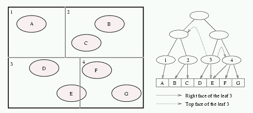
Figure 2: Space subdivision and the corresponding BSP tree with ropes
for the leaf 3. One of them is an indirect rope (points to the parent of
leaves 1 and 2).
The construction of ropes is very simple. For a given face and leaf, the BSP tree is searched starting from the root node. The traversal continues until we found a node whose splitting plane intersects the leaf-face for which we construct the rope. The rope points to this node. In each step of the traversal, we follow only the child that corresponds to our leaf-face.
Ropes point either to leaves or to interior nodes of the BSP tree. We call a rope that points to an interior node of the BSP tree an indirect rope. Every indirect rope can be replaced by the rope tree.
The rope trees are additional data structures exploited for the neighbour-leaf identification, leading to a faster ray-traversal algorithm.
The drawback of indirect ropes is, that the BSP subtree pointed to by the rope is a three-dimensional data structure. Therefore the splitting planes in the neighbour-node, that are parallel to the face where a ray exits the current leaf cell have to be traversed downwards. This is inefficient, because for a given leaf-cell we actually search for a neghbour-leaf on the leaf-face, which is a two dimensional searching problem. A rope tree is a pruned copy of the BSP subtree that the indirect rope points to.
The algorithm for building rope tree replaces the indirect ropes with the corresponding rope trees. Starting from the node the indirect rope points to, we perform the depth-first-search (DFS) on the BSP tree. Only the subtrees corresponding to the cells intersecting the face are visited during the DFS. Only the nodes whose faces intersect a given leaf-face are added to the rope tree.
In each step of the DFS, the possible cases are:
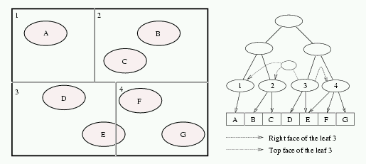
Figure 3: Space subdivision and the corresponding BSP tree with rope trees
for the leaf 3. In this simple case, the rope tree is only a copy of the
BSP subtree.
In order to exploit rope trees during ray-casting the traversal algorithm for the BSP has to be modified. Assume the ray-traversal starts in certain leaf-cell. Supposing the ray is not terminated here, we require to locate the next leaf-cell pierced by the ray. First we determine the exit-face of the leaf-cell, that is intersected by the ray in its positive direction. Then we have to compute the exit-point on the exit face. We follow the rope tree corresponding to the exit face. To traverse the rope tree, we have to compare the position of the splitting plane with the exit-point of the current leaf-cell and follow the appropriate child.
We incorporated the rope trees into the ART rendering package, which is a ``collection of Objective-C libraries that provide a wide range of functionality suitable for graphics applications'' (see [7]). The implementation of BSP trees was made by Robert F. Tobler and it is quite interessant. Each inner node of the BSP tree contains the position of the splitting plane, two pointers to the children and also the direction of the splitting planes of the children. The interesting thing is, that the direction of the splitting plane is stored in the parent of the node, not in the node itself. This allows faster traversal of the BSP tree, since for each direction of the splitting plane, the code for traversing the node is slightly different. The code for each direction of the splitting plane is stored in one procedure. Since the direction is stored in the parent, it knows which of these proccedures to call (the pointers to these procedures is stored in an array which is indexed by the direction of the splitting plane). This brought additional memory requirements to the imlementation of ropes, because for each rope, we have to store also the direction of the splitting plane of the node the rope points to. For large scenes, this is quite significant.
In this section we present and discuss the effeciency of our implementation of rope trees. As testing scenes, we used the ones included in the ART package and also a scene composed of randomly generated triangles. All BSP trees were constructed with maximal depht 20 and the number of primitives for a node to become a leaf was 4. The measurements were conducted on AMD K6-II PC, 333 MHz, 96 MBytes RAM in the Linux operating system. The results are given in Table 2. Table 1 describes the meaning of the measured variables.
| NP | Number of polygons |
| M | Memory required for the spatial data structure |
| TP | Time requred to buid up the spatial data structure |
| TR | Time requred for rendering itself |
| S1 | Speedup when using rope trees (rendering only) |
| S2 | Speedup when using rope trees (rendering and preparation) |
| Scene | NP | Method | M (kB) | TP (s) | TR (s) | S1 (%) | S2 (%) |
| Octagon | 10 | BSP | 1 | 0.01 | 137.05 | ||
| Ropes | 2 | 0.02 | 135.87 | 0.91 | 0.91 | ||
| Cylinder | 100 | BSP | 4 | 0.05 | 78.37 | ||
| Ropes | 17 | 0.05 | 77.74 | 1.75 | 1.75 | ||
| Cylinder | 10000 | BSP | 387 | 7.65 | 79.93 | ||
| Ropes | 2678 | 8.07 | 77.74 | 2.74 | 2.02 | ||
| Teapot | 3751 | BSP | 231 | 3.28 | 70.76 | ||
| Ropes | 1857 | 3.54 | 64.68 | 8.55 | 7.86 | ||
| Banana | 4586 | BSP | 336 | 5.05 | 66.20 | ||
| Ropes | 2753 | 5.41 | 61.54 | 7.04 | 6.04 | ||
| Eagle | 4684 | BSP | 497 | 6.69 | 124.06 | ||
| Ropes | 3588 | 7.26 | 121.64 | 1.95 | 1.41 | ||
| Small random | 10000 | BSP | 109 | 2.30 | 81.74 | ||
| triangles | Ropes | 834 | 2.40 | 76.05 | 6.96 | 6.65 | |
| Large random | 10000 | BSP | 893 | 12.63 | 142.55 | ||
| triangles | Ropes | 6630 | 13.88 | 137.12 | 3.80 | 2.69 |
The results in Table 2 show that the ray-casting with rope trees is always faster. The speedup varies from 1 to 8 percent and it is influenced by the size of the scene and by the nature of objects' materials. For the diffuse surfaces the speedup was lower than for the specular surfaces. The price we have to pay for speedup is the amount of memory required for the spatial structure. The memory requirements is increased approximately eight times.
We have shown that the ray-scene intersection test is faster with rope trees. Although the speedup is not very significant, it has some practical use especially for large scenes with a lot of specular surfaces.
[1] A. Fujimoto, T. Tanaka, K. Iwata. ARTS: accelerated raytracing system, IEEE Computer Graphics Applications, 6:16-26, 1986.
[2] A. S. Glassner. Space subdivision for fast raytracing. IEEE Computer Graphics Applications, 4:15-22, 1984.
[3] J. Goldsmith, J. Salmon. Automatic creation of object hierarchies for ray tracing. IEEE Computer Graphics Applications 7:14-20, 1987.
[4] M. R. Kaplan. The uses of spatial coherence in ray tracing. 1985. SIGGRAPH '85 Course notes no 11.
[5] S. J. Kingdon. Speeding up ray-scene intersections. Thesis, Univ Waterloo, 1986.
[6] J. D. MacDonald and K. S. Booth. Heuristics for ray tracing using space subdivision, The Visual Computer, 6(6):153-166, 1990.
[7] Robert F. Tobler. ART: Advanced rendering toolkit. http://www.cg.tuwien.ac.at/research/rendering/ART/
[8] V. Havran, J. Bittner, J. Žára. Ray tracing with rope trees. Proceedings of 13th Spring Conference on Computer Graphics. Comenius University.