Abstract
We
focus on semantic description of 2D/3D scenes. Several problems with common
formats, especially with VRML, are discussed. MPEG-7 is a relatively new
standardized tool providing extended features in semantic description of
multimedia content. Short introduction into its capabilities is made. How does
it help us to solve our problems with semantic description? We use MPEG-7
format to store semantic graphs related to an appropriate scene. The
application for creation, editing and visualization of MPEG-7 description is
implemented. Special emphasis is laid on the functional model of the
application enabling extensibility in the future. Problems with visualization
of MPEG-7 description are discussed in an extra section. The results of our
study are summarized in the list of implemented features.
Keywords:
Semantic description, Functional model, VRML, SVG, MPEG-7, Visualization,
Semantic graph.
1 Introduction
An
incommensurable amount of audiovisual information is becoming available in
digital form, in digital archives, on the World Wide Web, in broadcast data
streams and in databases, and this amount is steadily growing. There is a
variety of binary and textual (XML based) file formats representing the
audiovisual information and in practice we want to use both of them. The
quality of information often depends on how easy it can be found, retrieved,
accessed, filtered and managed. The data itself usually do not have any
semantic description that would help us to easily recognize its content. Thus
we need a standard generic tool, which will be used to describe the multimedia
content and on basis of this description we can find, retrieve, access, filter
and manage audiovisual information. MPEG-7 is the answer to this need. The
MPEG-7 standard, formally named “Multimedia Content Description Interface”,
provides a rich set of standardized tools to describe multimedia content. Both
human users and automatic systems that process audiovisual information are
within the scope of MPEG-7.
2 Goals
We are
aimed at MPEG-7 semantic description of 2D/3D scenes. A modular system, which simplifies
or in ideal case automates creation and editing of semantic description should
be proposed. Modularity is understood as the possibility to use various
visualization concepts for one semantic description and support for more data
formats. Primarily we take into account following data formats: VRML, X3D and
SVG.
3 Related work
The
MPEG-7 semantic description is not the only way to represent meta data. RDF
(Resource Description Framework) is another format for similar purposes. It was
developed by W3C and provides interoperability between applications that
exchange machine-understandable information on the Web. Another example would
be the DAML+OIL language which
uses ontologies.
4 Use case
Scenario
1: User needs a 3D
model of a building or only its part. The system knows his context and the
context is used together with the user’s query as an input to the system, which
will generate an adequate 3D scene. What is adequate is determined using the 3D
model itself together with a semantic description stored in MPEG-7 format. For
the user is this as transparent as possible. For the system’s functionality is
it fundamental to have appropriate semantic description to be able to recognize
the functional structure of the 3D model.
Scenario
2: The user,
typically a construction site manager, inspects the construction yard while
having a mobile device at disposal. He can similar to scenario #1 query the
system to provide 2D blueprints in SVG format. Then he can compare the reality
to the plan and make some notes in a form of annotation directly to the SVG plan.
While he generates the annotation, additional semantic information is recorded
at the same time. The semantic information is again in MPEG-7 format and will
later be used when searching for relevant data.
Scenario
3: This scenario is
in fact an extension of scenario #2. The user can besides annotating the SVG
blueprint also directly edit it (or a working copy of it). When selecting or
editing an object, the user will be visually notified of other semantically
related objects. For example when moving a wall, all windows and doors in the
wall must be moved also. When moving a table, all chairs should be moved too,
and so on. For this functionality we again need a semantic e.g. functional
description of the model in our case stored in MPEG-7 description.
5 Problem description
In all
scenarios we work with semantic description of given scene. The question is how
the structure of semantic description looks like and how it could be created.
In our work we focus to the process of metadata creation.
5.1 Problems with other
formats
An ideal situation for our scenarios would be the case when the semantic (logical and functional)
description of a 3D/2D model would be a part of the data format. VRML and SVG
formats are unfortunately not the case. We can derive some information about
the functionality of the modeled object from the geometrical structure. Usually
there is a correlation between how the object is modeled and how it really
works. Nevertheless we cannot rely on it. Let’s have a look at some aspect of
the authoring process, which helps us to obtain the semantic information from
the geometry. For example, a scene in VRML format has a hierarchical structure.
The author usually groups a set of functionally related objects not only due
the logical meaning but also for easier manipulation. When creating bigger
scenes, smaller pre-defined entities could be used (PROTOs). Similar to the
object grouping, the PROTOs usually reflect a functional subset of modeled
objects. After using them we obtain logically built scene matching to the
functionality of the 3D model in certain way.
Despite of the grouping and PROTOs techniques,
the hierarchical structure of the VRML format is restricted in expressing
abilities. We will demonstrate the limitations on a simple example. Having two
rooms – room A and room B – in VRML there is no way how to express that their
common wall belongs into both rooms. Only one room could be chosen as a parent
of that wall. This problem is shown in Figure 1. In VRML there are 2 possible hierarchies of the
scene depending on placement of the wall “Wall X” which conduces to a little
semantic incorrectness, because a part of the semantic information is lost. The
DEFed node “Wall X” can be added to the scene graph only once, otherwise we
would get more independend objects.
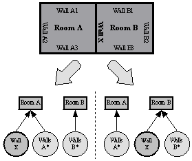
Figure 1. Limitation of VRML in abilities to express semantic information
Semantically correct solution of this problem
would be presence of the wall “Wall X” in both rooms – “Room A” and “Room B” in
the object hierarchy. This is shown on .
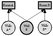
Figure 2. Correct semantic description of the scene in Figure 1
We cannot do this in VRML by simple applying
two times the USE construction for “Wall X”. In that case the resulting scene
graph would contain two independent walls. For example moving one of them would
not affect the second one, because it could genarally be USEd under another
transform node.
This problem is not the only one in VRML. Other
than hierarchical relations cannot be specified at all. For example it is
impossible to specify that from one room can we go through the door to another
room, because it is pure semantic property of the door object.
All of the problems discussed in this section
are comprehensible, because the purpose of VRML is modeling of virtual reality
rather than creating of semantic description for the modeled scene. But we can
solve such a problem by using additional information about semantics of the
scene in MPEG-7 description.
5.2 MPEG-7 semantic
description
In this
chapter we focus on the structure of the Semantic graph section of the MPEG-7
format. There are 3 basic tools in MPEG-7 standard used for description of
semantics of multimedia content:
·
Semantic
Entity – Describes
scenes or semantic entities in scenes. The definition is recursive and
based on level of detail so that we can go as deep as necessary.
(room->bed->pillow->feather->…)
·
Semantic
Attribute – Describes
attributes of semantic entities and semantic measurements in time and space.
(color, material, position, etc.)
·
Semantic
Relation – Describes
relations among semantic entities.
The structure of MPEG-7 description can be
understood as a graph where nodes represent semantic entities and edges
represent semantic relations. Semantic graph gives us information about
semantics of the modeled scene. Figure 3 shows an example with semantic graph of a scene with
two connected rooms. It consists of connections of semantic entities (=nodes)
with appropriate relations (=edges).
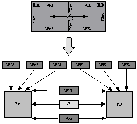
Figure 3. Modeled scene and resulting semantic graph
There are
2 types of entities shown in the semantic graph:
·
Objects
(walls W* and rooms R*)
·
Events
(connection P)
Walls are the only real existing objects in the
scene above. Rooms RA and RB are entirely imaginary objects built from
surrounding walls (and optionally from other objects inside them), but in the
semantic graph they have the same type and are handled similar to walls,
although they need not to have an equivalent description in the original format
of the VRML scene. On the contrary events are completely different. In our case
connection P is an event, which reflects an ability to move from RA to RB and
from RB to RA.
With regard to previous cogitations we take
into account following two groups of relations:
·
ObjectObjectRelation – binary
relations between two objects
·
ObjectEventRelation
– binary relations between one object and one event
In each group there are many predefined
relations in MPEG-7 standard, but the norm does not strictly prescribe which
relations should be used in various real situations. The interpretation of each
relation depends on the concrete purpose of the developed application. The use
of the MPEG-7 semantic description depends on the application. It seams to be
useful to combine the semantic description with ontology database. The ontology
then describes the existing objects in a given area while the semantic
description glues those abstract objects to the real data format.
6 Solution
In this
chapter we analyze basic functionality of the application working with MPEG-7
description in more detail. Alternative visualization techniques and further
capabilities of MPEG-7 are introduced. Extra emphasis is laid especially on
interaction with the user and modularity of the system. Finally concepts for
plug-in components and for use case depended dictionaries are discussed.
Our system should run on various operating
systems and devices (desktop computers, PDAs, etc.). In order to ensure
platform independency it is necessary to use convenient programming language.
We have chosen Java, which is platform independent and suits well to our mobile
scenarios.
6.1
Basic functionality
We are
trying to integrate the visualization of the multimedia format (VRML/X3D/SVG)
with the visualization and creation of MPEG-7 description. The application
layout will contain two basic windows. The first will display an appropriate
data format, the second one will work with MPEG-7 description. When editing the
MPEG-7 description the user must be able to interact with the 2D/3D model.
Selecting an object in the model will result in selecting an appropriate entity
in MPEG-7 description and vice versa (see Figure 4).
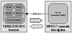
Figure 4. Basic application model
When
selecting a semantic entity describing an object “Room” all objects associated
with it should be selected in the browser. In our case it will be all the walls
surrounding the room and its contents. Selection means highlighting in a way
defined by the browser. The browser receives a message from the MPEG-7
component with description of objects that should be selected (resp.
deselected) and processes the selection. For example in 3D model material
properties (color, transparency, etc.) of objects could be changed. Similarly
in 2D some visual properties of the selected objects will be changed.
User’s context based work
Context
is a set of information about location, time, user, device used, environment,
sound, brightness, etc. The generated MPEG-7 description can be enriched by
some information from the current user’s context. The problem of collecting and
updating of the context data is not the theme of this work.
Level of detail (LOD) based work
Let us
imagine selection in an opposite way than on Figure 4. The user selects an object in the browser and is
awaiting selection of an appropriate semantic entity in MPEG-7 component. The
question is what is the appropriate entity. (see Figure 5)
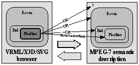
Figure 5. Problem with selection
After
selecting a feather in the browser are we awaiting selection of the feather in
MPEG-7 component. But not every time. According to the created semantic
description there is a possibility to go into less detailed levels in the
semantic graph. The user could choose “Room” level for example. After that he
wants to work only with rooms and their components do not interest him at this
time. He would be awaiting selection of the whole room instead of feather. The
problem is that the browser does not know anything about semantics of the scene
and is not generally able to recognize it. In consequence of that it cannot
decide which objects to select based on the chosen LOD. This is a work of the
MPEG-7 component. (see Figure 6)
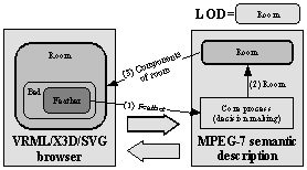
Figure 6. Selection based on LOD
The
browser never performs the selection after clicking on an object in scene
immediately. First it must send a message with information about selected
object to the MPEG-7 component and wait for reply. The core process in MPEG-7
component decides which objects should be selected according to the LOD and
also according to other conditions and state of the MPEG-7 component. One of
the conditions will be discussed in the following section.
Level of abstraction (LOA) based work
Level of
abstraction offers a different view to the same data. It is determined by a
degree of generality the user wants to work with when editing the MPEG-7
description. For example he might want to work only with objects made of wood.
Their shape, color, etc. are not important at that moment. His query to the
system will be: “show me all objects made of wood”. How does the system use the
MPEG-7 description to accomplish this task? At first it needs to know the
properties of the objects. Every object must have a set of its attributes and
just according to the attributes the user can specify the LOA graph. (see Figure 7).
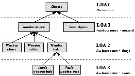
Figure 7. Example of LOA graph
The nodes
of the LOA graph must meet an inheritance criterion, which means that every
parent must be a generalization of its children. (Jane’s wooden bed IS a wooden
bed, a wooden bed IS a wooden object and a wooden object IS an object). We must
notify that LOA is not LOD, because LOD is based on containment instead of
inheritance. (A building HAS rooms, a room HAS beds and a bed HAS a feather,
etc.)
The selection functionality is similar to LOD.
The MPEG-7 component will search for appropriate values of attributes and
command the browser to highlight found objects. For example after selecting of
“LOA 2” (see Figure 7), the system is prepared to search objects with a
given “material” and “shape” attribute. And what happens when a bed would be
chosen in the browser? It depends on material of the bed. The system will
search for all beds, which are made of the same material as the chosen bed.
(because not each bed is generally made of wood).
We utilize the LOD and LOA for creation of MPEG-7
description. The most important part of our system is the MPEG-7 component
where creating and editing of MPEG-7 description takes place. In order to
simplify these actions as much as possible, the user needs to see the results
in the original scene also. He can use the selection possibilities discussed in
the last section. For example he might want to create a new entity with all
computers in the building or on the 2nd floor only. He could change
attributes of objects in the whole group and so on.
6.2
Visualization of MPEG-7 description
There are
many ways for visualization of MPEG-7 description. Some of them will be
introduced in this section.
A semantic description might be very
complicated. Although the MPEG-7 format is based on XML, eg. it is text based,
the complexity of the description will often exceed the human’s ability to get
if from the native form. When visualized it is much more understandable. We
make fewer mistakes and expose more.
Visualization
criteria
Because
of the free enhancement possibilities for entity and relation types, in various
real situations the graph could be much more complex and it is generally
impossible to see it whole. There must be some a set of criteria defined by the
user specifying the graph area to display.
Three of them imply directly from the
functionality of MPEG-7. Thus the semantic graph may be filtered according to:
1.
Entities
with given attributes (shape, color, material, position, etc.)
2.
Given
types of relations
(components of objects (1:N), connections of rooms (M:N), etc.)
3.
Both
entities and relations
1.
Filtering by given attributes of entities is quite easy and could be done by
“cutting” entities in semantic graph which do not meet a specified filter
criteria. With this we can filter some objects we do not want to see in the
visualized semantic graph.
2.
Filtering by relations is more interesting. Dividing the relations into the
categories (1:N) and (M:N) rapidly changes the structure of semantic graph. We
will discuss the consequences in more detail in the following paragraphs. It
has a direct influence to the visualization used.
3. The
last possibility arises after combination of previous two points. It is the
most powerful solution, because we can filter the semantic graph according to
attributes of objects and relation types.
Visualization of
(1:N) relations
We
discuss here visualization of semantic graph after applying filtration
according to some (1:N) relation. In this case we visualize only that parts of
semantic graph connected by the specified (1:N) relation. These are mainly
relations based on containment. As an example we can take the same scene as on Figure 3. The difference will be in the visual form of its
semantic graph. Due to the filtration by relation type (1:N) we know, that the
new semantic graph is a tree (see Figure 8). In order to eliminate cycles from the original
semantic graphSG, the walls “WX1” and “WX2” must occure twice. This does not
cause any problems, because they are actually the same objects with the same
MPEG-7 description.
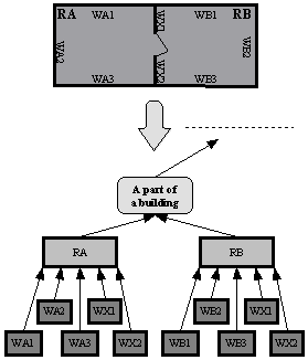
Figure 8. Visualization of (1:N) relations
This
helps us in our application, because visualization of trees is easier to
implement than a general graph visualization. Moreover in our implementation we
can use existing API with sophisticated GUI for trees.
Visualization of (M:N) relations
(M:N)
relations are more difficult to visualize. The structure of the resulting
filtered semantic graph will not generally have a tree structure. Instead it
will be a general graph. The consequence is that we must have an engine which
working with general graphs. As an example we can imagine relation “connection
of two rooms”. Because each room could be possibly connected with an arbitrary
amount of other rooms, the relation must be (M:N). The data structures indicate
certain similarity with databases and could be described by ER (Entity
Relationship) diagram which is a common way of representing data in databases. Figure 9 shows an appropriate ER diagram for this situation
and its alternative version with an additional entity “Connections”. The second
version provides better view on how the data is really stored in the memory.
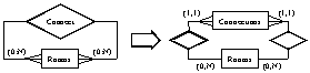
Figure 9. ER diagram for relation „connection of two rooms“
Due to
the Figure 9, the simplest way how to visualize relations (M:N),
in our case all connected rooms, would be an interactive table. It would
contain rows from the entity “Connections”. In comparison with graph, table has
some advantages. It is easy to implement in Java, very transparent and simple
(see Figure 10).
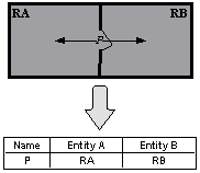
Figure 10. List of (M:N) relations in a table
Second solution would be the use of graphs.
Generally after filtration of the semantic graph we obtain a new one with
unknown topology. Thus we can use a component working with general graphs. But
sometimes it is possible to recognize its topology in a certain way. We could
test it for planarity for example. In this case some component for
visualization of planar graphs (2D grid) would be used. For example rooms in a
building may have planar topology and it would be better to work with a 2D grid
than with a general non-aligned graph. (see Figure 11)
Further we could use components working with
other special topologies like 3D grid, full graph and so on. 3D grid would be a
good tool for visualization of connections between rooms in all floors of a
building in which the third dimension would be used to visualize stairs, but it
is not easy to implement and not so transparent like 2D grids.
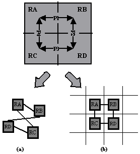
Figure 11.
Visualization of (M:N)
relations in (a) general graph, (b) planar graph (2D grid)
The
purpose of using special components for different topologies is clear. Besides
better transparency, the creation and editing of MPEG-7 description can be
better adapted and automated. Especially in the case of planar graphs there is
an existing component system for 2D grids in Java which is another advantage.
6.3
System modularity and plug-in concept
Due to
the existence of various components for visualization of MPEG-7 description
(1:N, M:N) it must be possible to use various MPEG-7 components in our
application. Furthermore we need also support for various components for
visualization of the scene (=browsers),
because we want to describe both 2D and 3D scenes. On Figure 4 we assumed the existence of only one such a component
in both categories (browsers and MPEG-7 components), but the application model
of the real system must be enriched according to Figure 12.
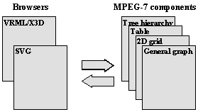
Figure 12. Enriched application model
Our
system uses so called plug-in concept. The core of the system is responsible
for handling the events from other system components and for maintaining the
data structures. Additional components provide the UI functionality along with
the visualization of the edited data and semantic data. The visualization
components use a defined API of the system’s core. This architecture results in
a great flexibility and extensibility. Anyone in the future may create new
component simply by implementing predefined interface. Already existing
components can be used when a wrapping code is created. The new component can
by dynamically added without the need of recompiling the whole application.
6.4
Dictionaries
We are
aware of certain application dependency of MPEG-7. For example relations
“connection” could have different meanings in different branches. In
architecture they would be used in conjunction with rooms in order to define
“connection of 2 rooms”. But in geography the relation would be defined perhaps
as “connection of 2 towns”. Due to this fact dictionaries with meanings of
relations and entities should be made just according to the concrete use case.
Actually the dictionary is a template with explanation of all meaningful
relations in the appropriate field of application. All of this is in the scope
of MPEG-7 standard, because it is very generic and its concretization is not
far to seek.
The second reason why we need dictionaries is a
correctness securing of semantic description. For example while the user is
creating “connection of two rooms”, it is strictly defined that the objects
figurating in this relation must be rooms. Thus they must meet a common
criterion for values of attributes, in this case shape=room. A short
dictionary is demonstrated in Table 1:
|
Relation name |
Type |
Left entity |
Right entity |
|
Connection of 2 rooms |
(M:N) |
Shape=room |
Shape=room |
|
Room definition |
(1:N) |
Shape=room |
Shape=wall |
|
Room equipment |
(1:N) |
Shape=room |
Shape=(bed OR table OR bookcase … |
Table 1. Example of a dictionary
7 Implementation
Implementation
of some features discussed in the last chapter was done and successfully tested.
Here is a list of them:
1.
VRML/X3D
browser
2.
MPEG-7
components:
·
Tree
hierarchy ((1:N) relations)
·
Table
((M:N) relations)
3.
Modular
system + additional class providing access to MPEG-7 description (see next section)
7.1 Implemented modular system
As mentioned
above cooperation between browser and MPEG-7 components must be accomplished.
We could:
1.
Bind
the browser and MPEG-7 components by calling their methods directly (without
inheritance - naive solution)
2.
Generalize
the classes with using of interfaces and listeners (better solution)
3.
Do the
same as in 2) + insert another class between the browser and MPEG-7 components
and allow access to the stored MPEG-7 description to this class only. The
communication between the browser and the MPEG-7 components would be
accomplished through this class.
Solution
number 2 seems to work fine but it has one major disadvantage. The MPEG-7
components would have to directly access the stored MPEG-7 description and this
would complicate the implementation of plug-in concept for new MPEG-7
components in the future. Therefore the most complex solution (number 3) was
chosen (see Figure 13).
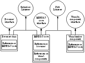
Figure 13. Implemented application model
The
cooperation of components works according to the described model in section 6.1 Basic functionality, but only basic capabilities for selection were
implemented yet.
8 Conclusion
We have
built a system for visualization and creation of MPEG-7 description. The key
features of this system are:
·
Modularity
·
Interactivity
(browser + MPEG-7 components)
·
Extensibility
in the future
The
product of our application is a XML file with MPEG-7 description which can be
then used for any purposes of any application operating with metadata.
8.1 Future work
In the
future we will focus on
·
Implementation
of user’s context, selection based LOD and LOA (see 6.1 Basic functionality)
·
Improvement
of visualization capabilities of MPEG-7 description, especially for relation
types (M:N) (see 6.2 Visualization
of MPEG-7 description)
·
Implementation
of more plug-in components (see 6.3
System modularity and plug-in concept)
·
Implementation
of dictionaries (see 6.4
Dictionaries)
·
Distributive
(and collaborative) work
Acknowledgements
This work is partially sponsored by the German Federal
Ministry of Economics and Technology (BMWi). It is part of the BMWI-funded
project MAP (Multimedia-Arbeitsplatz der Zukunft), one of the key projects in
the area of Human-Technology-Interaction (MTI). The focus of MAP is the
development of technologies, components and new methods for multimedia
interactions that use novel and intelligent systems offering assistance and
supporting delegation. More information: http://www.map21.de.
References
Balfanz D. (2002), Automated Geodata Analysis and Metadata Generation, in Proceedings of SPIE Conference on Visualization and Data Analysis Vol. 4665 (pp. 285-295)
Li J. Z., Ozsu M. T., Szafron D. (1995), Query Languages in Multimedia Database Systems, Technical Report, The University of Alberta Edmonton
Mikovec, Z., Klima, M., & Slavik, P. (2002), Manipulation of Complex 2D/3D Scenes on Mobile Devices, In Proc. of the 2nd IASTED International Conference Visualization, Imaging and Image Processing (pp. 161-166), Anaheim: Acta Press. ISBN 0-88986-354-3
Mikovec, Z., Klima, M., & Slavik, P. (1999), Structural and semantic dialogue filters, In Proc. of the 2nd International Workshop Text, Speech and Dialogue (pp. 280-285), Plzen: Springer-Verlag, ISBN 3-540-66494-7
MPEG-7, from ISO/IEC JTC1/SC29/WG11 2000: http://mpeg-7.com; http://www.cselt.it/mpeg/
W3C Consortium, XML: The Extensible Markup Language, from http://www.w3.org/XML/
W3C Consortium,
SVG: Scalable Vector Graphics, from http://www.w3.org/TR/SVG/
W3C Consortium,
RDF: Resource Description Framework, from http://www.w3.org/RDF/
W3C Consortium,
DAML+OIL: Ontology language, from http://www.w3.org/TR/daml+oil-reference
Web3D Consortium,
VRML: The Virtual Reality Modelling Language, from http://www.web3d.org/Specifications/VRML97/
Appendix
Screenshots
of our application with their explanation are shown in this chapter. We focus here
on visualization of relations:
1.
(1:N)
– component hierarchy
2.
(M:N)
– connections between rooms
1.
In the
first case we use a tree hierarchy which is implemented by a java class JTree.
The user can build the tree based on containment which means that every child
is component of its parent. Interactivity works within the bounds of both
windows – 3D scene (left window) x MPEG-7 component (right window). Selection
of an object in the scene results in selection of an appropriate MPEG-7
description in MPEG-7 component and vice versa (see Figure 14).
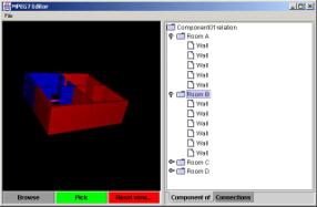
Figure 14. Visualization of tree hierarchy of objects, „Room B“ object is selected
2.
(M:N)
relations are visualized by the simplest way – in a table. As a demonstration
we take into account connections between rooms only, but it is possible to use
the table for visualization of other (M:N) relations also. Interactivity woks
similar to previous example. The user can select objects in one window and see
the response in the other one. (see …)
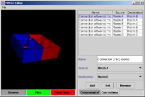
Figure 15. Visualization of connections between rooms, connection „Room A“ ó “Room B” is selected